Getting panel cooling wrong in either direction is costly. Undersized cooling causes rapid electronic components failures and catastrophic plant downtime during summers; oversized cooling wastes massive capital. Correct sizing — based on a proper engineering heat load calculation — delivers 10+ years of reliable, trouble-free operation for your manufacturing facility.
The Master Formula
Every industrial panel cooling calculation starts with this fundamental thermodynamic heat balance equation:
Required Cooling Capacity = Panel Heat Load + 25% Safety Margin
"Getting panel cooling wrong in either direction is costly. Undersized cooling causes immediate hardware failure; oversized cooling wastes massive capital. Precision engineering prevents both."
Step-by-Step Calculation
Step 1 — VFD Heat Loss (Biggest Contributor)
Every Variable Frequency Drive (VFD) dissipates approximately 2.5% of its rated motor power as heat inside the enclosure due to internal switching transitions. This is typically the largest heat source in any automation panel.

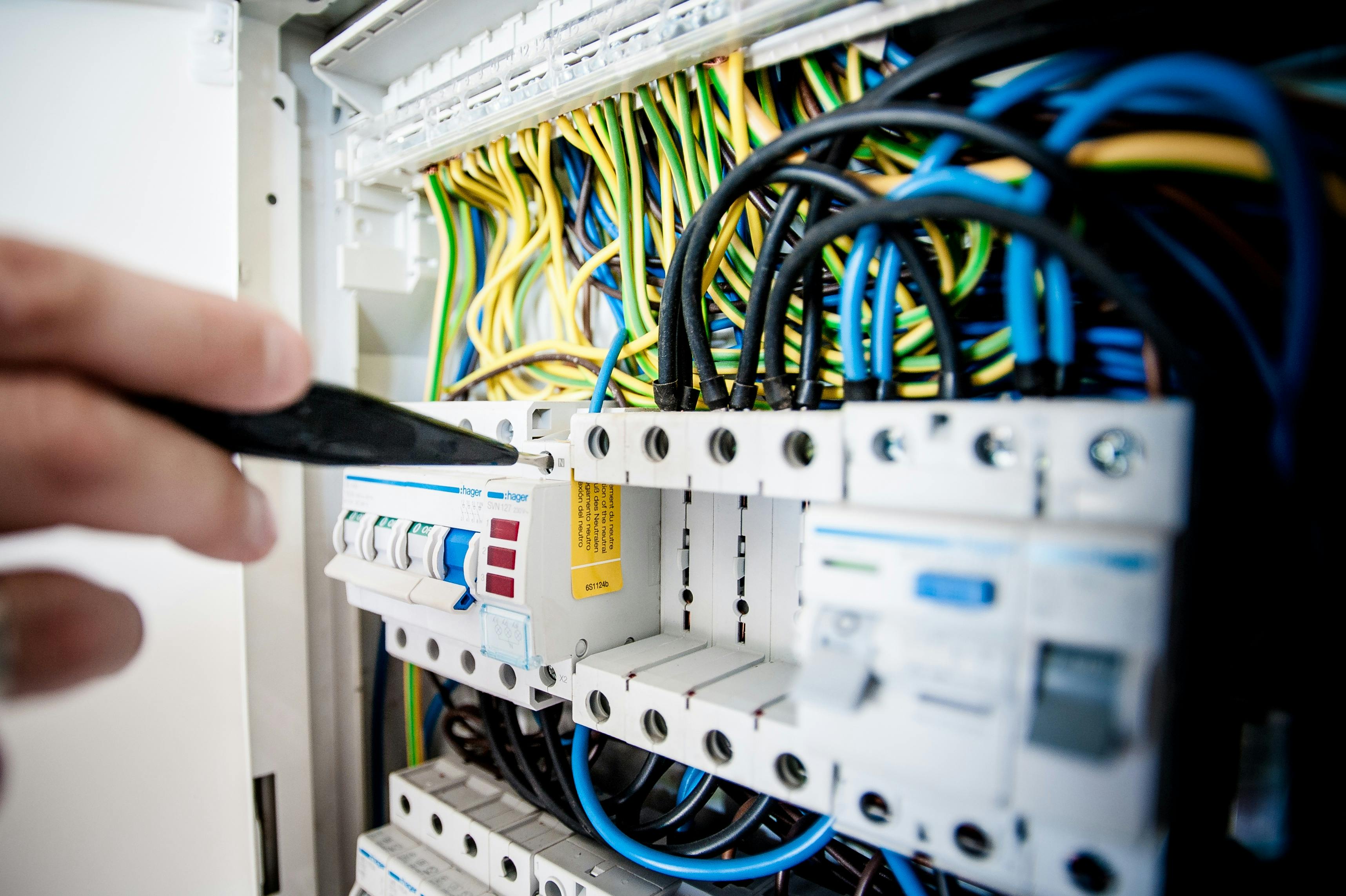
Figure 1: Sizing panel cooling requires evaluating cumulative internal losses from active electronics under peak seasonal load conditions.
Step 2 — AC Choke / Reactor Loss
Line reactors (chokes) used to filter power quality harmonics dissipate approximately 0.5% of total motor power. While small, this is consistently overlooked during panel design, leading to systematic undersizing of cooling equipment.
Overlooked Summer Risk Factor
Engineers routinely omit choke losses. For a 37kW drive, this represents an extra 185W. Multiplied across three or four drives, this equals the difference between an air conditioner keeping up or tripping on high pressure during summer.
Step 3 — Other Components
Other elements of control panels contribute auxiliary heat loads:
- Control transformer — 10–20W per kVA
- Power contactors — 5–15W each
- Overload relays — 3–8W each
- PLCs, modules & HMIs — 10–50W total
- SMPS / Power supply — 15–40W
Step 4 — Ambient Correction for Indian Climate
The ambient temperature surrounding your electrical panel changes cooling capacity requirements:
- 35°C–40°C ambient room temp → No additional correction needed
- 40°C–45°C ambient room temp → Add +10% to total load
- Above 45°C → Add +15% to total load
Step 5 — Add the 25% Safety Margin
This engineering buffer accommodates peak summer conditions, dynamic machine spikes, future panel modifications, and prevents the cooling system from running continuously at maximum duty cycle.
Worked Example — Real Indian Plant
Panel: 2 × 37kW VFDs with line chokes, 3kVA transformer, PLC, contactors, relays
Step 1 (VFD losses): 2 × 925W = 1,850W
Step 2 (Choke losses): 2 × 185W = 370W
Step 3 (Other): Transformer 45W + Contactors 72W + Relays 16W + PLC 55W = 188W
Subtotal Heat Loss = 2,408W
Step 4 (45°C ambient correction, +10%): 2408 × 1.10 = 2,649W
Step 5 (+25% margin): 2649 × 1.25 = 3,311W
Selection recommendation: Haima PAC3500 (3,660W rated capacity)
Quick Reference — PAC Selection Guide
A quick rule-of-thumb comparison guide for sizing Haima's auto-clean closed-loop panel air conditioners:
Conclusion
Panel heat load calculations are not optional guesswork. Selecting cooling equipment based on volumetric size or panel volume is a recipe for premature device failure during hot Indian summers. By applying this simple, structured 5-step engineering formula, you can ensure stable cooling parameters, secure component lifespans, and completely avoid unplanned factory shutdowns.